By Society Staff –
Reprint with Permission Only
Carter ThermoQuad Operation and information
The Carter TQ was available in two sizes, rated according to airflow. The smaller of the two was rated at 850 CFM, and the larger was rated at 1000 CFM. At 1000 CFM, it was the largest “street” carburetor in terms of airflow when released, and it is still one of the most practical to this day.
These figures were arrived at by using primaries 1½“ in diameter with 13/8″ venturis, but the secondaries are huge, with twin 2¼” secondary bores, without venturis. These secondaries are controlled by an air valve similar to the one used in the Carter AVS carb and the Quadrajet.

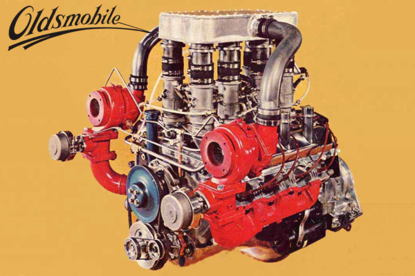
Carter ThermoQuad carburetor – first issue

ThermoQuad air horn viewed from the rear. Note that all components are attached to it.

Location of air valve tension spring

ThermoQuad secondary baffle plate removed.

ThermoQuad primary and secondary jets showing O-rings.
The TQ’s fuel bowl is not metal, but rather black-colored Phenolic resin. This is a great insulator, usually about 20° cooler than all-metal carbs. The fuel is cooled further because the metering system, with all adjustments except idle speed, is located in the air horn assembly on top of the bowl. As such, the metering system is suspended in the cool fuel. Beneath the plastic bowl is another gasket and an aluminum base plate that contains the throttle bores and idle adjustment screws.
The air horn contains the manual choke components, the air valve and its control and adjustment system, the twin float fuel inlet system and two sets of needles and seats, the accelerator pump, primary boost venturis, vacuum-controlled step-up piston and rods, and metering systems for high and low-speed operation. This arrangement makes jetting and other adjustments fast and simple.
The jets in some TQ’s are different; as they are held in place by “0” rings, not screwed in, and are removed by pulling lightly with a pair of pliers, and replaced by snapping them in. Primary and secondary jets are slightly different in shape and appearance, so they will not be confused.
The air valve secondary system is important to the operation of the carb. Since there is no venturi system in the secondary side of the TQ, an air valve is used to change air/fuel ratio by blocking or opening the orifice above the secondaries. As engine speed rises, the valve opens, and more and more fuel is drawn out of the nozzles by the air moving past them.
The Thermo-Quad has several controls and adjustments on the air valve which can be valuable tools for getting extra out of the carburetor. First, and most important, is the tension spring acting on the air valve to keep it closed when engine demands are not great enough to use the secondaries (just like the Quadrajet). One end of this spring is connected to the air valve shaft, and the other to an adjustable bushing on the outside of the carb. A locking screw and washer hold the bushing and spring once the proper tension is wound into the spring. Turning the bushing counter-clockwise gives more tension and clockwise gives less.
This initial preload or tension on the air valve determines when it will start to open, based upon engine load and speed. By slightly changing the tension on the spring, the air valve can be made to open sooner or later (at lower or higher engine speed) and thus, bringing in the secondaries at the best time.
A second control of the air valve is a vacuum operated diaphragm located on the side of the carburetor opposite the throttle lever. This unit acts as a dash pot, or to slow the air valve opening. It can control the speed at which the air valve is allowed to open, preventing bog if the secondary throttle valves were kicked open at high load, but low engine RPM. In certain racing applications this control can be disconnected, but for street use it is necessary for good drivability.
The diaphragm is connected to a lever riveted to the air valve shaft. An adjustable connector rod ties both together. Under part throttle conditions, with manifold vacuum above 6″ inches of mercury (HG), the diaphragm is retracted, preventing the air valve from opening. When the throttle is kicked open, vacuum drops the diaphragm is moved out to its extended position by an internal spring and the pressure of air valve trying to open, and this is when the dampening takes place.
There are two, small restrictions between the diaphragm unit and the carburetor. A .030″ hole is in the end of the metal tube fastened to the unit and a .016″ restriction is in the tube pressed into the base of the carburetor. Air must be drawn through these small holes as the diaphragm moves out. This causes enough of a delay to make the air valve open smoothly and at the proper rate to prevent a lean condition. By changing these restriction sizes slightly, (usually the one at the carburetor) the air valve opening rate can be changed.
The connector rod to and from the dashpot may be adjusted as well. With the diaphragm retracted fully and the air valve tightly closed, there should be no slack through the connector rod. In certain racing applications the engine may run better if the rod is made a little longer so the air valve opens quickly for a few degrees of rotation and then picks up the dash pot action. Either bending the connector rod or drilling out the restriction in the carburetor for faster opening can be done.
The last adjustment of the air valve is the tang that acts as a wide open stop for the air valve. This tang will hit a protrusion on the air horn casting as the valve reaches its fully opened position. Certain engine-manifold combinations will benefit by slightly changing the wide open position of the air valve. This is done by slightly bending the tang on the air valve so it contacts the wide open stop, sooner or later.
The air valve has bumps or dimples, which lay close to the large secondary nozzles in its wide open position. This creates a venturi effect around the nozzles to aid the flow of fuel and also affects distribution of the air/fuel mixture to the engine. There is a baffle plate that slips into the secondary throats between the upper and lower castings. It is positioned by notches molded in the Phenolic fuel bowl, parallel to the throttle shaft (shown in the exploded view of the carburetor). Proper distribution of air/fuel is controlled by this thin metal divider.
Most engines equipped with the standard log type manifold require the use of the baffle plate, but there are exceptions. Dynamometer tests showed a gain of over 30 HP on an engine with a “box” type manifold that runs at a relatively constant RPM when the baffle was removed.
The TQ has a double float setup, with two intake needles and seats fed by a common, centrally located fuel inlet at the rear of the carb. The center inlet design makes it easy to hook up a large 3/8″ fuel line from either side of the engine. The standard needle seats have .110″ orifices, but larger seats were available (usually only needed for all-out racing engines).
Both fuel chambers in the bowl are separated to minimize fuel slosh from G-forces, and the suspended primary and secondary metering jets are also centrally located in the fuel to make use of all available fuel in the bowl. The floats are pivoted at the rear of the carburetor to allow them to open under hard acceleration, assuring an adequate supply of fuel in the bowl at all times.
The accelerator pump system is also a unique design. Like the metering systems, it also is suspended in the fuel bowl from the air horn casting. The pump plunger is larger in diameter than previous Carter 4-barrel carbs to provide larger shots of fuel to the pump discharge tubes for better throttle response in high performance engines.
Instead of the usual drilled passages connecting the pump to the discharge tubes, the TQ utilizes a short piece of clear resin tubing. This tube eliminates several drillings which slow down pump reaction time, and it also makes it easy to see if a good, solid shot of fuel from the pump is happening, and makes cleaning the pump circuit easy.
The Thermo-Quad has an adjustable, universal type throttle lever, which bolts on with two screws and should fit just about any throttle linkage available; but it can be unbolted to make one as needed