How to Blueprint and Tune
Quality Quadrajets – Part Two How to Blueprint and Tune
Last month we outlined the essential ingredients in a rebuild of the Quadrajet. This month we will outline the major tuning and blueprinting methods used to increase your Quadrajet’s performance.
The Q-jet is a highly tunable carburetor. It was designed to be able to be used in applications from motor homes to high-performance vehicles. Actually, this ability works against the carb, because it befuddles the average tuner and generally turns them away from the carburetor.
But we will show you some quick and dirty methods to extract major performance gains with little expense. Remember knowledge is power – and in this case, we mean HORSEPOWER.
Please consider the listed vendors. Get the Doug Roe reference book shown if you really want to get the most from your Quadrajet.
Part Two – How to Blueprint and Tune Your Q-jet
First, we hope you read last month’s article and recognized that a simple rebuilding kit will not turn your 40-year-old carb into a performance king. We hope you followed that advice and are now staring at your properly rebuilt Q-jet sitting on your workbench – all shiny and new. Let’s now start with a few simple changes that will bear immediate fruit.
Float Bowl Pivot Pin. The Pivot Pin is held in place by the air horn. Spread the pin slightly so that the float/needle can’t climb out under high fuel pressure situations.
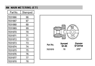
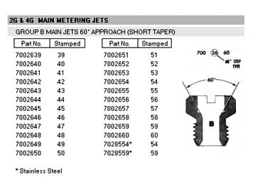
Primary Fuel Metering – Primary Jets. Don’t mix jets from other Rochester carbs. Different styles of jets are used in 2G, 4G, and 4M (Q-jet) carburetors. Quadrajet carbs have jets with a square shoulder under the head of the jet. 2G & 4G jets have a tapered shoulder under the head of the jet. 4M Main metering jets run from 0.066″ to 0.078″. Exception: 1970 W-Series cars use 4G 60-degree jets. (See charts at right for the jet sizes and part numbers).
The best way to start with a Q-jet performance increase is to increase the Primary Jet size. Each 0.001″ size increase in jet size equals a 1% increase in WOT fuel mixture.
Richening the Primary Jets can give a better surge off the line, but if one goes too “deep” in jet size changes, the car will slow down. (Since 1970 W-30 and W-31 use Rochester 4 GC 60 degree taper jets, they use smaller jet sizes. Follow the instructions below DO NOT USE REGULAR 4M jets in the OAI carbs unless you also change the primary metering rods).
Increase the Primary Jet size as follows (this is a baseline only – test after installing):
- 350 Stock except W-31 use 72 jets (#7031972)
- 350 Modified with cam equal to or better than the factory 308 degree cam use 76 jets (#7031976)
- 350 W-31 1968-1969 use 76 jets (#7031976)
- 350 W-31 1970 use 4GC 59 jets (#7002659)
- 400 Stock 1966-1969 except 1967 W-30 use 73 jets (#7031973)
- 400 W-30 1968-1969 or 1966-1967 400 modified 400 w/cam equal to or better than the factory 308-degree cam use 76 jets (#7031976)
- 455 Stock SMT except W-30 use 74 jets (#7031974)
- 455 Stock AMT except W-30 use 72 jets (#7031972)
- 455 W-30 AMT w/o triple taper rods use 75 jets (#7031975)
- 455 W-30 with triple-taper rods 1970 use 4GC 60 jets (#70002660)
- All 455 with a cam equal to or better than the factory 308-degree cam use 76 jets (#7031976)
NOTE: 1967 W-30 uses different carbs. Go up 2 jet sizes from stock for AMT, and 3 sizes for SMT. No higher than #7031977 (77 jets).
NOTE: 1965 400s used Rochester 4GC carbs. If you have changed to a Quadrajet, follow the instruction for the 1966-69 400s as shown above.
Install the new jets and test the car under WOT. (Make sure the Air Valve Wrap is set correctly – see below). If the car is “flat” on acceleration, try one-step leaner jets first (unlikely), and then go one step richer over the above recommendations.
Primary Fuel Metering Rods. Metering Rods sit in the primary jets and manage fuel flow. There are at least 15 different “A” taper Metering Rods and 18 “B” taper Metering Rods. 1970 OAI cars ran ultra-rare triple taper rods. Primary rods should not be changed in most cases.
The primary metering rods are identified with a stamped number and letter. (Example: “42B”). The number reflects the major metering area diameter in thousandths (0.042″) and “B” indicates that the rod has a double taper. The small diameter at the bottom of the taper is 0.026″ for all primary rods except those used in GMC motor homes. (See picture at right).
Save your changes in Primary Metering rods until all other blueprinting changes are tried. Many times, all Primary Metering rod changes will do is make the car really fussy on the street. If you do change them, start with your present rod and move one richer (smaller number) to see if performance improves. If the car is “flat” on acceleration try leaner first, then richer.
Those of you using the W-30/W-31 carbs with 4G jets and wishing for more adjustability should consider changing out your jets and rods because of the rarity of the triple-taper rods. Consider using regular 4M jets 7031974 or 7031975 as well as primary metering rod 7034849 (49B).
Secondary Fuel Metering – Secondary Jets. The secondary jets are fixed in place (non-replaceable). All metering is done by the size and shape of the Secondary Metering Rods.
Secondary Fuel Metering – Secondary Metering Rods. The secondary rod is the best place to work on improving the 4M. The chart at the right lists the myriad of available rods that were made. The rods outlined in gray are the most appropriate for performance use.
Secondary Metering Rods control fuel flow through three parts of the rod.
- Rod taper
- Rod small end diameter; and
- Rod small end length (called the “power tip”)
Oldsmobiles seem to like “short” power tip length and more taper as this gets fuel flowing soon after the rod comes off the seat. Thus, most Factory Stock through mildly modified cars can go immediately to the “CJ” Rod and see good results. Big-cammed cars can start with the “AX” Rods. At no point should you go past the “BY” or “CC” Rods.
Edelbrock stocks some rods that may be useful to you, however, we only suggest the CC-rod they stock (Edelbrock – PN 1950). The Carb Shop (www.thecarbshop.com) stocks a wide variety of rods that are more appropriate for Oldsmobile applications.
Secondary Fuel Metering – Secondary Metering Rod Holder (Hanger). The holder is used to raise/lower the rods when the Secondary Air Valve opens. These holders are letter coded from “B” to “V” at the end of the holder that is away from the hanger holes. with each letter indicating a 0.005″ rod height difference. The “B” rod has the smallest distance in height at 0.520″ with the “V” rod having the longest distance, at 0.615″. (See the chart at right).
The letter holder was selected at the factory to make the carburetor flow properly. Therefore, a carb with a “D” holder is not richer than a carb with an ‘M” holder. However, raising the secondary rods during their travel will richen the mixture below 3500 RPM, BUT not affect it above 3500 RPM. Lowering the secondary rods during their travel will lean the mixture below 3500 RPM and ALSO lean the mixture DRASTICALLY above 3500 RPM.
Thus, if you wish to richen the mixture below 3500 RPM, go back 1 or 2 letters. BE VERY CAREFUL GOING LEANER AS A LEAN ENGINE WILL RESULT IN DETONATION.
Only the “V” hanger has been the service replacement part (#7034522), so it’s back to the junkyard to scrounge hangers on either side of your hanger letter. If you have an “M” hanger; you want to find “J” through “P”, get as many different ones as you can.
NEVER BEND THE HOLDER to change its height. You cannot affect the fuel distribution evenly by this method.
Setting the Air Valve Wrap. The Air valve determines when the secondaries kick in. No matter what you did in the way of rebuilding or modifying your carb if the Air Valve wrap is not set correctly, the carburetor will either sag or bog or accelerate like a lazy 2-barrel car.
The instructions below REGARDING CLOCKWISE AND COUNTER CLOCKWISE – ASSUME THE AIR HORN IS OFF THE CARB AND IT IS SITTING UPSIDE DOWN ON THE WORKBENCH.
- First, insert a small screwdriver into the slot on the side of the Air Horn near the Dashpot/Choke Lever Arm. (See diagram opposite). Note the position of the screwdriver in relation to the Air Horn.
- Then loosen the Allen Lock Screw, while keeping the screwdriver steady.
Turn the screwdriver clockwise to free the Air Valve (it should flop back and forth freely). Tighten the Allen screw momentarily and ensure that the Air Valve is loose. - Now return the screwdriver to the slot, loosen the Allen Screw, and turn the screwdriver counterclockwise until the Air Valve just barely closes. (Zero tension). Note the position of the screwdriver. This is your starting adjustment position.
- Tighten the Allen screw and mark the position with a scribe or Magic Marker.
The normal air valve wrap is usually 1/2 to 3/4 turn counterclockwise in additional tension BEYOND the position that you just marked.
NEVER TIGHTEN the screw more than 1 full turn. This will stretch the spring and make adjustment impossible.
Air Valve Wrap Test Procedure. Regardless of how you have set the wrap on the bench, the only real way to get it right is to have some fun. This means some WOT from a dead stop! (Pretend there is a GTO or Vette alongside).
Accelerate the car @ WOT from a start with the wrap set at 1/2 turn, which we will call the “stock” position. This is your baseline. Now:
- Disconnect the vacuum hose from the choke diaphragm and plug the hose. Leave the spout on the diaphragm open. Make sure that the lever from the diaphragm to the Air Valve is not binding and works smoothly.
- Decrease the wrap in 1/4 turn steps. Make two runs at the same setting with the diaphragm disconnected on the first run and then connected on the second. If there is a difference, your diaphragm linkage may be misadjusted. Adjust, using the instructions in the Olds Chassis Service Manual until the results are as equal as possible. In some cases, less wrap may be possible with the diaphragm disconnected. Make this your “strip setting”. Don’t run the car on the street without the diaphragm connected.
- Decrease wrap in 1/4 turns until bog is detected. This usually occurs by 1/2 turn. If bog is felt immediately, (first run; tighten 1/4 turn). Automatic cars may require more wrap than manual transmission cars.
After you have reached your maximum wrap, with the best acceleration, NOW it is time to change your Secondary Metering Rods. Try going richer first, but don’t be afraid to go one step leaner too.
When you have baselined to the best set of rods, try readjusting the wrap in 1/8 turns. Air valve wrap changes the mixture in the low and mid-range of engine speed, so this is why you need to reset the wrap after you’ve changed the rods.
Once you have the best setting, replace your rod hanger with one letter closer to “B” Holder, then, if the improvement is felt, try one more. Never go more than 2. If no improvement was felt, try a holder one letter closer to “V” from your original.
Never go more than 2 letters in either direction if you change the rod holder from your original one in either richer or leaner letters.
If you are unsure of the result, go – to the original 1/2 wrap and try one step in richer rods and your original holder & work from there.
Doug Roe’s Book goes through many other tweakings that can be done to the 4M to increase its potential. If you need to run a 4M for a specific racing class and want to optimize it, we suggest that you have your carb rebuilt by a professional.
Vendor List:
- Edelbrock Company. Edelbrock Quadra-Jet Accessories. (www.edelbrock.com)
- The Carburetor Shop – California. Repair and
replacement Carburetors – gasket kits, etc. (www.thecarbshop.com) - Rochester Carburetors (Paperback) by Doug Roe
under $25 from Amazon (www.amazon.com)


Quadra-jet Exploded view with parts named
Click on the images below to enlarge them

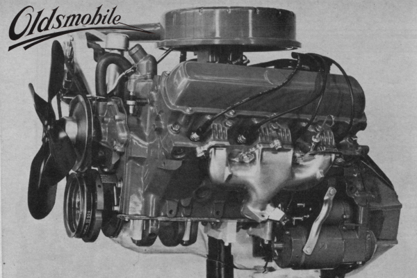
Rochester 4M Quadra-Jet Image 1
A typical Quadra-Jet
Rochester 4M Quadra-Jet Image 10
The Quadra-Jet Primary Jets. Note that the jet size is stamped on the jet AND that the last two digits of the part number reflects this size.
Rochester 4M Quadra-Jet Image 11
The 4GC 60 degree Primary Jets. Note that the last two digits of the part number reflects this size. The Carburetor shop stocks these jets.
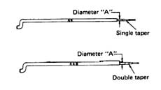
Rochester 4M Quadra-Jet Image 12
Shows the two types of primary metering rods. 1970 W-cars ran ultra rare triple rods.
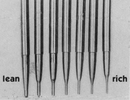
Rochester 4M Quadra-Jet Image 13
Examples of the different secondary metering rods. Note that the richer the rod, the thinner the tip. The taper after the tip controls the fuel delivery until WOT is reached.
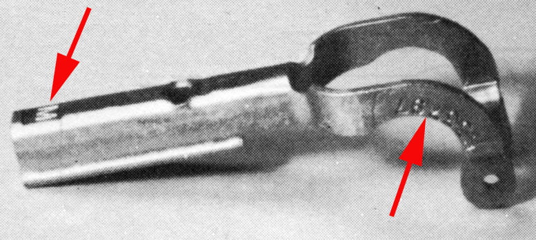
Rochester 4M Quadra-Jet Image 14
The secondary rod holder. Rod fit in the holes at right, right arrow points to the factory part number. Left arrow indicates the Hanger Code – in this case “M”. Hole in the center is where the screw fits to attach it to the secondary air valve
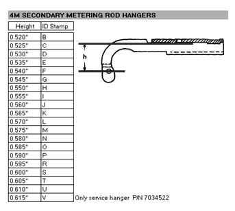
Rochester 4M Quadra-Jet Image 15
Hanger height and letter ID.
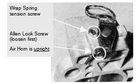
Rochester 4M Quadra-Jet Image 16
These two adjustment items set the wrap and lock it in place. Follow the instructions carefully!
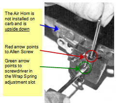
Rochester 4M Quadra-Jet Image 17
How to adjust the wrap.
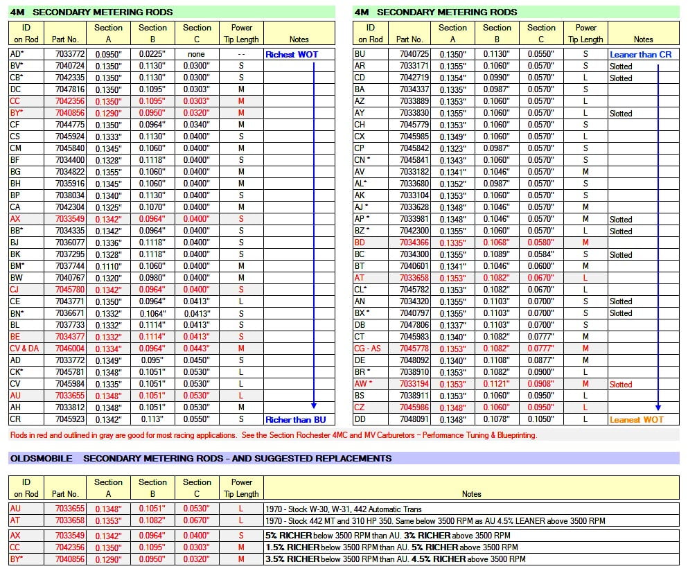
Rochester 4M Quadra-Jet Image 18
This chart lists all the potential secondary metering rods. The rods in gray are the best potential rods.